Friday, December 23, 2011

Cord Wood Saw

Yesterday, December 22, a 1/10th scale model of my father in law's cord wood, or firewood saw was completed. This was a rather simple model that was under construction a day or two less than a week.
In order to make the blade a blank disc of about 20 gauge sheet metal was clamped between a couple supporting discs and 80 teeth milled in with a "V" shaped cutter bit as shown above.
As a point of interest the blank was cut from the same piece of sheet of metal as was used to make the whimsical leg that I made and put in the flower bed last year, and originally it was the bottom of an evaporator cooler. (swamp cooler) I cherish every piece of metal I can get hold of to make things out of. The material for the angle iron and flat bar in the frame work was cut from the metal from an old washing machine or drier. The brass bolts that fasten together are a tiny size"0" and were ordered from Micro Fasteners in New Jersey.
Shown below is the father in laws original old saw that is now peacefully retired in the yard and only serves as a decoration, and reminder of days gone by.

Monday, December 12, 2011

8 Pound Baby Engine

Yesterday, December 11 2011 a new baby engine came to life at our house, and started chugging away. The engine was built from plans published in Popular Science Magazine in 1947, the year that I turned 14, but of course I did not have skills or equipment to build engines at that time.
The author of the plans was CW Woodson who was a prolific contributor of machinist articles back in the forties. He was an artiest by trade, machining was his hobby. Apparently iron castings were available for the engine at the time of the printing, but certainly not now. So I made wood patterns and poured castings in brass. This model was under construction for 5 weeks.
I worked from plans copied from original magazine pages, but believe it or not those old Popular Science magazines are still available for viewing on Google Books. To look it up if you are interested, type in Popular Science 1947, CW Woodson. You even get to see all the old ad's etc., a wonderful place to reminisce.

Saturday, November 5, 2011

Cement Mixer


October 30 2011 marked the completion of a model cement mixer. It was pleasant change after building several model engines. The inspiration to build it came from a plan that Rudi Kouhoupt had published some years ago. Although this model resembles Rudy's mixer. I did not follow his plan, and this one is about 25% smaller, and several construction details changed. This model ended up about 6 1/2" high as can be seen in the picture below.
Friend Mike Nay suggested that the mixer needed a companion wheel borrow to go along with it. About 4 days later it had that companion. With no prototype to copy it was built from memory, of ones seen in the distant past.
As a point of interest the ring gear was machined from brass plate and then parted off.
The bowl was machined from a solid piece of aluminum. All of the flat sheet metal parts for the mixer and also the wheel borrow were cut and formed from the sheet metal off an old washing machine .

Wednesday, October 12, 2011

James Watt Engine Model

After being under construction for over two months a model of James Watt's first engine has just been completed. This is not an exact scale model of that first engine built in 1788, but rather a representation that displays some of the features, like the sun and planet cranking gears that were used to avoid patent infringement. The original prototype had many firsts. Like it was the first engine to use steam under pressure to move the piston. It was the first steam engine to produce rotary power. It was the first engine to be rated in "Horse Power". The first to have the speed controlled by a fly ball governor. It was actually the beginning of the industrial revolution. James watt and Matthew Boulton formed a partnership, and after building this first engine, built hundreds more that were used in the British Isles and Europe. This first engine, by the way powered polishing machinery in Mathew Boulton's factory for 70 years. That is a long time for something of that vintage. The engine is now preserved in the Science Museum in London. Look it up on the Internet, there is lots of history about it.

Shown below are a couple short videos, one showing a close up of that governor that actually controls the speed of the model, and the other more of a look around as it is running.

Saturday, July 30, 2011

Ding Dong


After building several model engines this year I figured it was time to work in another metal sculpture. The inspiration for this one came from one of several pictures that Guy sent me from Disney Land while he and his family were vacationing there. (Shown below) While there are some similarities it is not a copy. The bells and Friar heads were cast from bronze. Some of the small decorative pieces from aluminum, and the rest is made of steel


If the cord is pulled slowly it produces a pleasant ding dong sound.
Now being equipped with both bells and whistles, our home is a pretty snazzy place.

Sunday, July 10, 2011

Spiritual Living

Gardening hint of the month: Growth Stimulants

The Begonias seemed to be a little puny this year so I made a trip to the Morgue and got some fertilizer. It is cheap and they have plenty. They will give you for free, all you want of people who do not pay their bill.

The Begonias ought to really start growing now, maybe even pass up that big green flower.

Actually the inspiration for this one came from the cover picture of a book that I had ordered.
It looked like someone had been smashed by an old cast iron bath tub.
I searched for a manikin, but when I found how costly they were, I decided t cobble something together myself. It is built out of the bottom pan of an old swamp cooler.

Hopefully we a can find another hint for next month. Until then Happy gardening!

Thursday, June 16, 2011

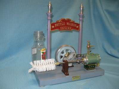
New Invention for Washing Bottles

As with any New Invention the first order of business is a design, which is easiest done at the drafting table using paper. Being lazy as I am, I tried to design using existing patterns that I had already made for other machines. It worked out pretty good. All I had to make new was a pillow block bearing support and modify the lettering on the sign.
Next step in the process was melting some metal to pour in the molds. That was on Memorial day and is was raining. Not a good day to be out in it.
Normally I move out on the driveway for melting, but water and melted metal does not get along very well so I opened the garage door, but stayed under the eves to keep dry.
Did not take long till the castings were done, with a moose thrown in for good measure. Don't know how he got in there except there was a little extra room in one flask.
Work proceeded a little bit each day until yesterday when the last part was completed. It is now ready for business. However it might be a hundred years too late. They don't wash bottles much any more. Dang, that is the story of my life.
Actually the real reason for building the thing was that I seen a picture of the crank motion that intrigued me. As you can see in the video it is a smooth running machine, but as with all scale models they seem to run too fast, and so you cannot fully appreciate the combined rotation and reciprocating of the brush.

Thursday, June 9, 2011

Jewel of a vice

On Saturday May 7th I hosted a gathering of Home Shop Hobby Machinists, and along with the "Show and Tell" of their projects, they were invited to bring items for swapping. George brought an old milling vise. It was in good shape but rather small, and had a rather large awkward base. No one seemed interested, so George just left it in trade for a box of Micarta that I had set out. At first I thought of adding it to the antique display, but after thinking a little more about it, I decided it could be converted into a vice for the shaper. I have been trying to find a better one than the old homemade one anyway.
The first order of business was to take the base and mount it on a face plate and machine a Tee shape groove.
Then the big mounting lugs were sawed off, and the bottom of what was left machined off smooth and level. The big screw that held it together was discarded and two smaller screws with Tee nuts now take it's place.
The end result was "Jewel" of a vise for the shaper. It fits and works just like it was made for the job. It closely resembles an original Atlas shaper vise. It even has the patina to look the part. I'm really pleased with it.
Presently I'm working on a new invention that I call a bottle washer engine, but you will have to wait, because I'm not ready to disclose much information on it.

Refinements to the Mini Lathe


Acquisition of the mini lathe happened at a slack time, and after building the first engine with it and getting acquainted, being spoiled as I am, I thought it needed some more refining. The square tool post that comes with the lathe is sturdy enough, but awkward to use because there is no height adjustment and no good way of changing tool bits back and forth to the exact position when changing between operations. Also the tail stock lock was by tightening a nut with a wrench. Because of such close quarters, it was difficult. I concluded it needed a quick change tool post and a cam lock on the tail stock. These things are available on the market place for money, but I was looking for something to make anyway, So I took the quick change off the big lathe and dissembled it to see how they work. Then a trip to the drafting table to sketch up a mini version.

The cam lock was built first. It was a pretty simple project, and really smoothed out the unlocking moving and re locking of the tail stock. It is almost a one move operation now.


Next came the quick change tool post. It was a little more effort, but turned out nice.
To start with 4 tool holders were made. That is about the minimum, that a person would want to get by with. I have 19 for the bigger Jet lathe. But besides tool bits, there are all sorts of attachments on them. Once the post is made, holders can be added as needed.

The mini has not been used a lot, but enough to know that the new refinements are are a worthwhile addition. Whats more I built them myself.


Tuesday, May 3, 2011

Mini Stuff

Last month when the Home Shop Machinist magazine arrived it contained a Harbor Freight ad with some coupons for equipment at very attractive prices. One of them was a 7"x10" Mini lathe. I do not really have a need for one because my 13"x40" Jet lathe will do everything a mini will do, but I have always wanted one because they are like babies, cute, however it is hard to justify something on that basis. In a moment of weakness I went to the Harbor Freight store over in Orem and a mini lathe followed me home. When I opened the box, I found that like all brand new babies it was covered with a layer of slick icky gooey stuff, so the first order of business was a bath to clean it up.

After clean up, it was time to start getting acquainted with the new baby. I started by making a tool bit height setting gauge, as seen below.
Then a storage rack was attached to the chip guard for the tools and accessories.

All that preliminary work done, it needed to be tested, so parts for a "Mini" engine were machined on it. Oh, what fun! It was like using a toy that really works. I was quite favorably impressed with its performance. The engine was completed yesterday afternoon. The head bolts, by the way are size "0", little bigger than watch screws.

And finally here is a 3 second video to show that it runs. I had plans to attach it to a wood base, but it is so smooth and well balanced, that it does not need a larger base.


Friday, April 15, 2011

Joseph Bernays engine of 1878

Some time ago I seen a picture and video of a Bernays engine on Lindsay Publishing website that has an interesting motion. I do not know anything about the engine, whether the originals were a successful design or not. On the website it indicated that the engine had been exhibited by Joseph Bernays of London at the Paris Universal Exposition in 1878. However it looked like a good canidate for a model so I built one. It was finished yesterday. It runs beautiful, and will throttle down so you can see the parts in motion other than a blur. It will be a fine exhibit for the display room.

Just in case you are wondering, that dark thing on the bottom is a "Footing". I have heard all big engines need a footing to support them.

Sunday, February 20, 2011

Stirling's First

Having built a number of Hot Air Engines over the years, both scale and generic, I decided it would be interesting to build a scale model patterened after Robert Stirling's first engine patented in 1816 and built in 1818. It was used to pump water out of a rock quarry. There are no pictures of the actual engine and the illustrations found in a number of books were drawn from the patent drawings. Models have been built of this engine, but I have never seen any plans of such, so I proceeded to draw up my own.
In addition to working up the linkage mechanism, I had to accommodate the materials that were on hand. Simply something that most model makers do anyway.
There were concerns if it would even run because the timing was somewhat different that most hot air engines and not not too much could be done to change it and still look like the illustration.


When it was to a point where the engine part was complete, heat was applied to the hot end with a small Butane torch, and as soon as it was heated sufficiently it ran beautifully.
Being satisfied with the initial test, construction proceeded until it was finished and placed on display, as seen in the first two pictures.

Saturday, January 22, 2011

Twin Cylinder Geared Wobbler


Another fun little engine has just been completed. It is not a scale model of anything that I know of, simply an interesting mechanism to watch in action. The inspiration to build it came from watching a video of a similar engine on the Internet. It is nearly all brass, and weighs in at three pounds. Construction time was about 2 weeks, considerably quicker than the last model.

Here is a short video of it in action.

Tuesday, January 11, 2011

Corliss Steam Engine Model


Last week, after being under construction for 4 months, a scale model of a Corliss Steam engine was completed. At one time Corliss Engines were the state of the art workhorses of heavy industry. There were two of them that powered all the machinery in the sugar factory in Centerfield where I grew up. They had Manila rope drive from the flywheel to the jackshaft on the second floor, with pulleys and belts running everywhere. The engines were so dynamic with all the valve motion, etc. Is there any wonder that I was fascinated with them even as a small boy. The factory and engines are gone now. I was of the last generation to be able see them working, and to be able work in the same factory with them thumping away. My model is not a scale engine of the sugar factory engines, but still a Corliss design.


Thermo Acoustic Engine

Way back on June 1 2007 I completed a Thermo Acoustic Engine that actually runs. Just don't ask me how or why, because I don't know. I had bought a book authored by Warbrooke over in New Zealand about building one, and I built it per the instructions, but that engine would not even attempt to run. I gave it up as a hoax. Then later I seen some videos on the Internet, and also acquired another book written by Roy Darlington in England. Roys book had a short 4 page chapter on them. No plans, but a good description, so I proceeded to build another one, and by golly it actually runs under its own power. Not very fast, but it does run. Here take a look.