Wednesday, June 3, 2015

FROMENT ELECTRIC MOTOR

While looking at pictures of old electric motors, there was a picture of the first motor built by Paul Gustave Froment in 1845. The design looked as though it would make an interesting model.
The flywheel was the first part. I wanted an excuse to try the new rotary table that I had received for the mini mill just a few days prior. It worked great, the table is now justified.
A image was down loaded from the Internet of a reproduction that someone had built. It was almost identical to the image of the original motor, except much clearer. The image was re sized so the the flywheel measured 2 1/2" diameter, same as the one I had machined. From there everything could be made in proportion without the need of making a drawing.
       Yesterday the final parts were completed and assembled, and of course it needed to be tested with power. Connected to a 6 volt battery it ticks over at a nice leisurely pace. Take a look at the video.


Friday, May 22, 2015

PACINOTTI MACHINE

    In the same book where I found the Bourbouze motor there were other electrical devises, one of them called the Pacinotti Machine. It looked interesting and after a bit of reading about it, I found that it was invented by Antonio Pacinotti, a professor of physics at the college in Pisa, Italy about 1860. The original machine was designed as a dynamo, but Antonio found that it would also operate as a motor. The invention turned out to be quite significant, although Antonio did not realize what he had stumbled onto until several years after he built it. The principals are still in use today.
     The illustration in the book was enlarged to the size that I wanted to build the device, so that I could simply take measurements right off the picture. For your reference the rotor is about 2 1/2" diameter.
    Construction began by making rotor and stator parts out of 1/4" thick steel plate. The stator part needed to be a ring with the two halves separated by nonmagnetic material.  Antonio used brass so I did the same.
    The 16 coils on the rotor were separated with wood wedges, same as the original. If not the first, this was one of the very first devices to use a commutator. I made this one by cementing copper strips to an insulating hub, and then wrapping with thread cemented in place. I would suspect that is pretty close to how the original was made.
    Finally on the 19th of May it was completed, but I simply could not get it to run as a motor. Then this morning at the suggestion of my friend Paul Spencer, I checked the wiring connections, and I had two of the wires connected wrong. Soon as I exchanged them it took off running like a champ. Here is a video. I have no idea what caused it to slow down near the end, perhaps a poor connection to the power source or something?


Friday, April 24, 2015

BOURBOUZE BEAM MOTOR


While thumbing through an old issue of Modeltec magazine I ran across some line drawing sketches of early attempts to build electric-magnetic motors. One in particular, the Bourbouze, intrigued me and a quick search of the internet and I found that Google had an ebook with a picture of the engine, so I ordered a printed copy. Using a copier I enlarged the picture so it matched the size of a flywheel casting that I had on hand. Enough drawing was done to work out magnet dimensions, and other measurements were taken directly off the picture.
Magnet spools and slide switch were machined out of Micarta material.
Winding of the magnet wire onto the spools was done using the mini lathe. It has variable speed and would slow down to a comfortable speed for winding. The wire was tensioned and guided onto the spool with a gloved hand. The lathe is reversible, and two spools were wrapped right hand and two left hand. The wire was covered with a layer of cloth and bound with sewing thread, and then given a coat of varnish to seal it in, in a manner to the originals.
The slide switch was a project all by its self. There are probably better ways to make a switch, but I was trying to duplicate the original somewhat.
     When Bourbouze built his motor about 150 years ago, he modified an existing steam engine with magnetic coils in place of pistons and a slide switch in place of a slide valve. Bourbouze's engine ran, but electricity at that time was usually provided by batteries because dynamos and generating equipment had not yet been perfected. Batteries of that time were expensive, and not very efficient. Consequently Bourbouze's motor was not competive with other power sources, such as steam engines.
    I'm sure the picture that I followed to build my model is not of the original engine, but rather a model that someone before me had put together. Still I'm pleased with it. It runs fine on a 6 volt battery, and is completely different than anything I've built before. It is a good addition to the display room.


Monday, March 30, 2015

SAFES

Hard cash is getting to be such a scarce commodity these days I decided I had better build a safe to keep mine in. Actually I had a couple old post office mail box doors that needed something to do.
It was a fairly simple job that just required cutting some wood and fastening it into a box. The wheels were machined out of scrap pieces of aluminum. Wheels were not really necessary, but give an interesting touch. Looks like the old original safes. The whole job only took a couple days. Much quicker than the previous project that took 4 months.


Monday, March 23, 2015

CAROUSEL

After completing the MACHINE last November I was sort of surfing the internet looking at things trying to get an idea for another project when I ran onto images of carousels. Hundreds of them and no two seemed to be exactly alike. That gives a builder a lot of leeway in incorporating ideas of his own. A very labor intensive project, yes, but I went for it anyway and four months later there is one sitting on display in the living room as seen below.
The above picture is a close up while still in the workshop.

I could go into a detailed rundown of its construction,but that would get real boring in a hurry, so I'll just show a few highlights.
The base or foundation was built out of 1/2" Baltic Burch plywood. The base holds the drive mechanism, the transformer for the lights, and the sound system.The entire rotating part of all carousels is carried by a single shaft in the center that supports a structure of wood and metal. Even the lower deck hangs from this structure.
There needs to be gears to turn the cranks that cause the animals go up and down, and they had to be made special for the job.

Below is a picture of the column for the model, with a slip ring that provides power for the lights. you also see the Bodine gear motor, drive pulley, and the belt. That yellow belt is out of an old clothes dryer.

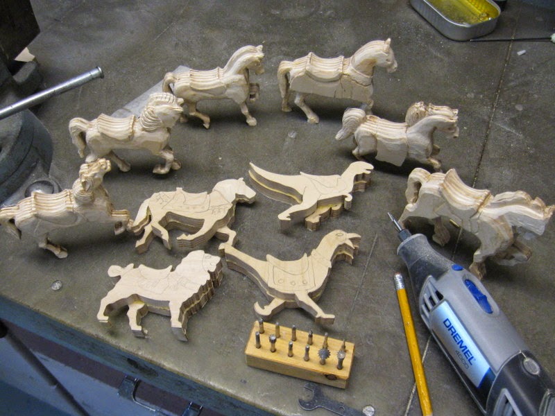
The 24 animals were carved out of Baltic Birch plywood. The reason for using plywood is so the thin sections would have strength in all directions. A left and right side was sawed out for each one using the scroll saw and the two haves glued together. shaping and detailing was done with a Dremel tool using various shaped burrs. It was not a fast operation, it took a whole month to create the animals.
Painting was done with acrylic tole paints and then embellished with little plastic gems from the Hobby Lobby Store. There are over 1000 of those little gems on this project. That makes it sparkle.
About half way through the project, Darlene my bride of 61 years ago passed away after a lengthy struggle with dementia. In honor of her I adopted a family theme and decided to decorate the fascia with pictures of our family members. Rather than the most current, I tried to use the most happy looking ones. It required learning a new computer skill of sizing and cropping each face into an oval border. It was a slow process, and about the time I became proficient at it I was done.

And finally a video of it in action. By the way the amplifier for the sound system is designed for a motor cycle, and the music is stored on a USB flash drive. However it seems to work just fine for this application.


Saturday, November 22, 2014

THE MACHINE

 In my library are several books showing all sorts of mechanical movements, and I got an idea that building a number of those movements into a machine would make for an interesting project to work on. And it did. The above picture show the results after working at it for about a month and a half. The two pictures below are the side views.

 Here is a video of the mechanisms being cranked into action.


Friday, September 26, 2014

RINGBOM HOT AIR ENGINE

After seeing a Ringbom engine operating at a hobby machinist gathering and being intrigued with it, I decided to build one myself. I already had a booklet about them in by library written by Dr. James Senft. According to the information in the book they were invented by Ossian Ringbom in 1907. However there is no evidence that any of the engines were ever built. Using a patent drawing Dr. Senft had worked up a set of construction drawings for a miniature working model, which I used as a basis for this model, except I doubled the size, and changed some of the materials to be able to use what was on hand.
The cold end of the displacer cylinder was machined out of solid stainless steel. The hot end is a piece of drain pipe or tube. The displacer is a small shaving soap container. The power cylinder is a piece of automobile shock absorber, and the flywheel is a roller that I picked up at a swap meet, etc. etc.
     It is rather strange. Below operating temperature, both starting and stopping it rocks back and forth in half revolutions.
However after it reaches operating temperature it runs in full circles, and it will run either direction.
In this video it is running at about minimum operating temperature. Slightly more heat and it will run faster.

Wednesday, August 27, 2014

REPLICA OF HENRY FORD'S FIRST ENGINE

For a long time I've had a desire to build a replica of Henry Ford's First engine. The engine is a simple looking thing built mainly of pipe fittings before Henry ever got started into making automobiles. I'm sure he just wanted to see if he could build a gasoline engine that would run, and he did. The year was 1893.
    Just as I was looking for another project The Home Shop Machinist magazine came out with a construction article on the engine. What better time to build one than now? First thing to do was search the Internet and I was able to find a couple pictures and other information. My engine is not an exact duplicate of the original. More of a compromise between the article and the pictures that I found. But a close representation.
The first order of business was to gather what materials were on hand and then a trip to the hardware store for a few pipe fittings.
Every day I managed to do a couple machining  operations or make a part or two.
Here is a close up of the timing gear, exhaust cam, and sparker switch (breaker points).
Finally the completed engine. In an attempt to duplicate the original the parts were mounted on an old weathered board.
Considerable time was spent hand cranking the engine and using starting fluid. I never could get it to pop more than once or twice, and I was beating my hand against the board. So I built a cranking adapter that fit the electric drill. This made it so the engine could be cranked faster and easier, and I finally got it so it would run a couple seconds at a time on it's own.
     A whole week was spent trying everything I could think of to get it to run continously. Finally an adapter was made and it was switched over to propane. Same old story, just a few pops at first, but the more I kept trying and adjusting the better it ran until, well look at the video for yourself.
During the process I learned a few things perhaps I can go back the the drip lubricator and get it to run on gasoline, but out of time for today. Actually I'm pretty excited to have it running at all.


Friday, August 8, 2014

KIMBLE STEAM ENGINE

Time for another engine project and this time the Kimble Engine out of Elmer Verburg's book was selected, because it is different. Rather than a piston it has a vane.
The engine was invented by Emory Kimble near the end of the 1800s and manufactured by the Comstock Manufacturing Co. in Michigan. The original engines ranged in size from 2HP to 45 HP, and were produced at a rate of about 25 per month. In addition to the US, shipments were sent to a number of foreign countries.


The model is a simplified version of the original, and is constructed of brass, stainless steel, with an aluminum base. It was under construction for about a week.

Sunday, July 27, 2014

MODEL LEHMAN HOT AIR ENGINE

It was time for another model engine. This time I picked a Lehmann Hot air engine because it has such an interesting linkage motion.
The Lehmann engine was developed and patented in Germany, but the particular one I built the model of was manufactured in England by W H Bailey Co. under a license agreement around 1860.
Construction was carried out looking at an illustration that I copied out of a book. It is not and exact scale model, but a pretty close representation. At first glance it looks complicated, but is really a pretty simple engine.
To start I needed to find some tubing for the cylinder and displacer. I had a 5" long piece of tube from a Bimba air cylinder that could be used where the power piston operates, but it was not long enough for the hot tube, so I tried rolling up some sheet metal for that and also the displacer. When they turned out OK, I proceeded with the patterns for the castings.
I only needed to make patterns for the water jacket and stand it sits on. I was able to use a base pattern from previous models.
A graceful curved spoke flywheel like was used on the original German engines was poured, but I changed my mind and ended up using a straight spoke, round rim wheel like was used on the Bailey engines. Fabricating and machining proceeded a little bit each day until yesterday it became a complete and working engine.

 Except for the bolts and screws, it was built entirely from scraps, even melted down some old motorcycle parts for the castings. It turned out great and is one of my best running hot air engines. From what I've read about them, the original engines were some of the best. It has been a most satisfying project. Construction time approximately 5 weeks.


Monday, June 16, 2014

MINI ENGINE


While trying to think up another project to work on I built a Mini Engine that did not use up a lot of time or material. It was finished Father's June 15, so I have been telling everyone that it is my new Baby.
It really runs to, but goes so fast it is just a blur, take a look.
Got the engine done, and posted on the blog, and I'm still thinking about a next project, so I do not know if it helped or not.

Sunday, June 1, 2014

ELGIN CUTLASS PISTOL

   For something unique and different this time I made a replica of an Elgin Cutlass Pistol. They were invented in 1837 by George Elgin, at a time when close combat was often with the use of knives, or swords. Adding a gun seemed like would be quite an improvement. The US Navy purchased 150 of them, and some were issued for use in the 4 year Wilkes South Pacific Exploring Expedition.
   They were the only pistol to ever be fitted with a knife, and the first to use a percussion cap, which gives them some historical significance. However the small number manufactured, is probably a testament to their usefulness in combat.
 Construction started by finding some good pictures of the pistol on the Internet, then enlarging them to the full size to be used as patterns. The main frame was cut out of the ugliest scrap I could find. Actually the only one I had with enough mass to it.
 Bits and pieces were slowly pared away to get down to the desired size.
 The barrel simply started as a strip of 7/8" steel plate. This pistol was a smooth bore, so it only required drilling it out to .540" (54 Caliber). Lot of chips milled off to get it to octagon shape.
The blade was sawed out of 11/32"plate. That was too thick for the blade, but needed to be about that thick to look right for the knuckle guards which are integral.
The excess thickness was milled off the blade in the milling machine using a fly cutter. Not a very efficient way of manufacturing, but OK I guess for a one of a kind replica. It got the job done.

 The lock parts were hidden from view in all pictures, so I had to guess at what they looked like. You see what I ended up with in the above picture. It works good and that is what counts. The main spring was cut from a piece of 2" wide x .048" thick heavy strapping or banding material. At first it was too soft so it was hardened and tempered. Now it works fine.
            The handle or grip was carved out of a piece of walnut.
Finally this morning after being under construction for a month it is complete and ready to be placed on display, as shown in the first picture of this posting. Although probably not the best fighting weapon, hopefully it will be a good conversation piece.